Line Map
Description
Found in the Edge Detection group of parameters of Line Kit Settings file.
Line Map is a technique that allows you to generate an outline from a dedicated per-object or per-layer texture. The texture is not directly rendered to the end camera, instead, it is only used in intermediate outline rendering stages as a source of color differences.
Using Line Map you can conveniently generate inner lines on the objects, like between tiles on a floor or between bricks on a wall. You can also use it to generate outlines on the edges of the objects that otherwise would be difficult to detect by the other techniques.
Line Map is one of the primary and most powerful sources for generating outline in Line Kit.
Line Map controls
Line Kit has two sources of line map:
- Line Map on Objects - the texture is applied to the material of the object.
- Line Map on Layers - the texture is applied to the layer mask of the object.
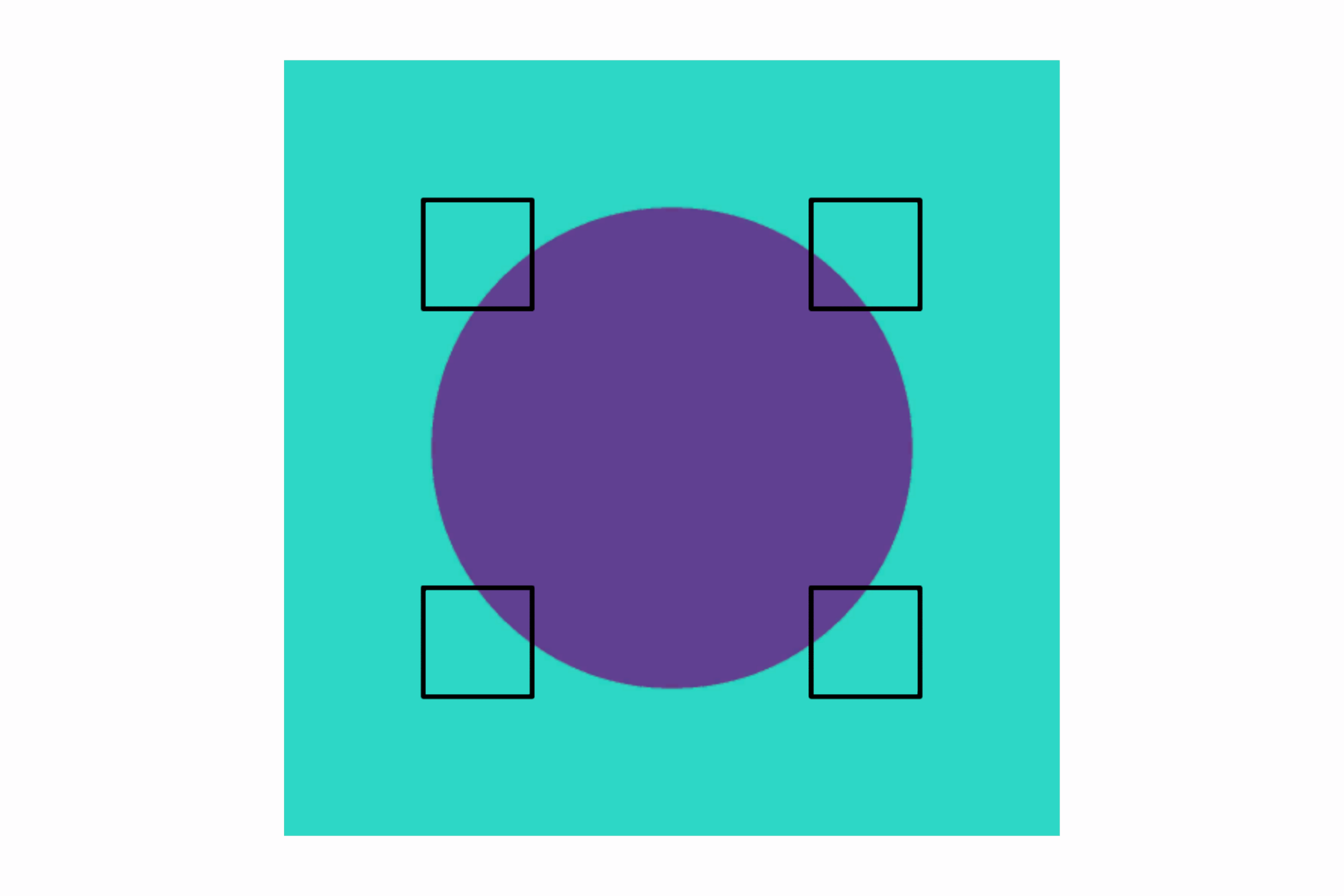
The colors of the texture for Line Map technique in Line Kit are used in the following way:
- Red color differences create an outline,
- Blue color makes the opposite — it removes a line.
- Green color is used to create a face filled with the color of the outline, set in Line Appearance → Color parameter.
Line Map on Objects
Description
The idea is to use a utility texture inside of a material and apply this material to the UV unwrapped object. The UV faces (islands) of the object are distributed over the texture in a way that the faces that we want to have a shared outline are placed in the differently colored areas of the texture. The faces that we don’t want to have a shared outline are placed in the same colored area of the texture.
This way, the faces that have the same normal, depth and camera (albedo) color can have a shared outline. Moreso, a single face can have inner lines.
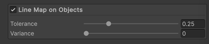
Line Map on Objects interface
If you go to the Debug Output menu and select Line Map On Objects, you will see how the texture is used for the outline generation, specifically how the UV faces of the models are colored in different shades of red by being previously distributed over the texture in a 3D editor.
Line Map on Objects in action in the Debug Output mode
Parameters
- Tolerance - Tells how different should be the red colors to cross the threshold and generate a line.
- Variance - The range of color difference in the red channel of the Line Map at which the outlines transition from non-existent to fully visible. If the variance is set to zero, the outlines are binary: either they are visible or not. If the variance is set to a value greater than zero, the outlines gradually appear as the red channel difference between neighboring samples increases.
Line Map on Objects pass selected in Debug Output
Line Map Material
The texture is set in a material and set as the 2nd material in the Mesh Renderer component of the object.
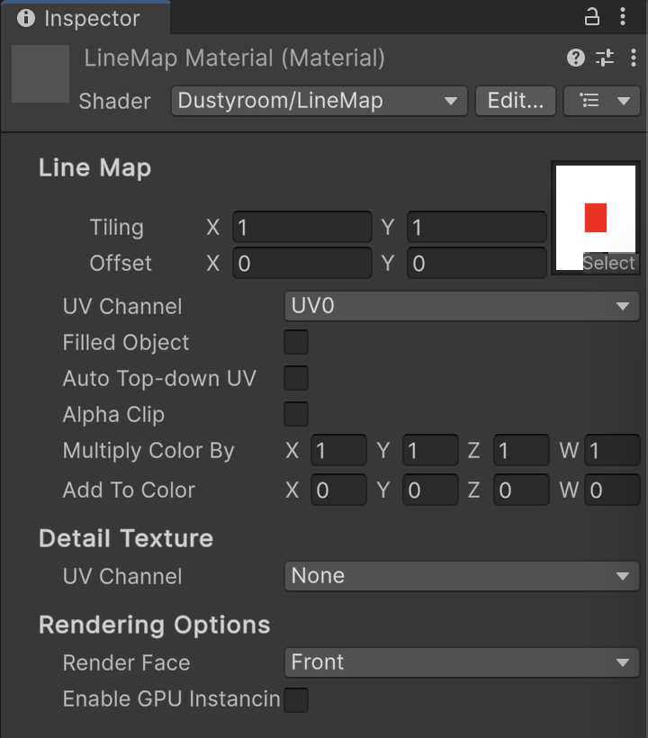
LineMap Material interface
To set up a Line Map material, please follow these steps:
- Create a new material.
- Set the shader to
Line Kit/Line Map.
- Set the texture to be used as source of color differences for the pre-mapped faces of the mesh. It is described in detail further on this page in Best Practices.

- Set it as the second material in the Mesh Renderer component of the object. The order of the materials is not important.

Line Map material has selectable UV channels for the Line Map and Detail textures.
Having separate UV channels for the Line Map texture is useful when your main UV map responsible for and albedo texture doesn’t align with the Line Map texture. For example, this way you can have the lines inside the mesh face even if this face is primarily unwrapped to fit the albedo texture and/or has its own tiling and offset settings.
The Detail Map texture is used to add some detail to the lines, like a noise or a pattern.
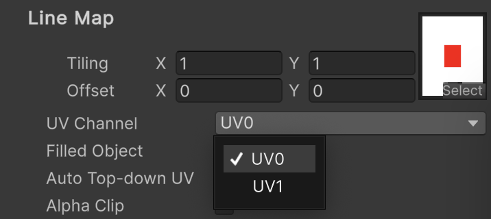
LineMap Material — menu for selection the Line Map texture UV channel
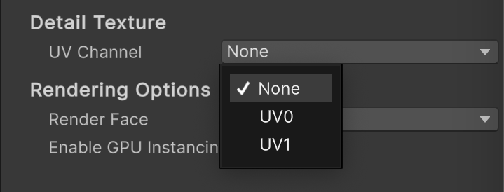
LineMap Material — menu for selection the Detail texture UV channel
In an example below we are using a plane mesh with two UV channels. The first UV channel is used for the albedo texture and the second UV channel is used for the Line Map texture. The goal is to have the lines inside the plane mesh and not on the edges of it, which would be the expected result otherwise.
These are the two textures:
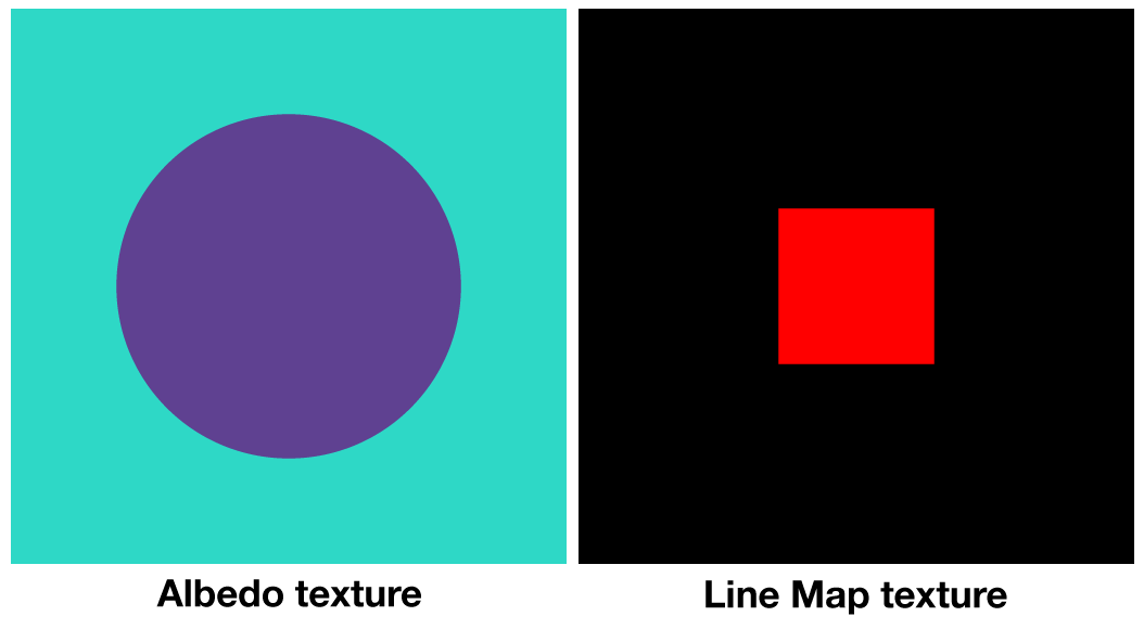
Usage example. Albedo and Line Map textures used on separate UV channels of a plane mesh
The plane mesh is made of 4 qudrants (please see gif below).
- UV channel 1 (used for albedo): all four quadrants are neighboring on the whole UV face.
- UV channel 2 (used for Line Map): each quadrant occupies the whole UV face.
This is the result:
Usage example result. Mesh with the lines inside the face of the plane mesh.
Line Map on Layers
Description
It is more convenient and efficient performance-wise to have one common Line Map texture on multiple objects. If the use case allows, use this instead or in addition to Line Map on Objects. It uses its own texture, while the Line Map on Objects uses the texture set in the material of the object.
We use this technique in the following sample scenes:
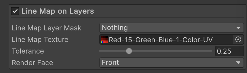
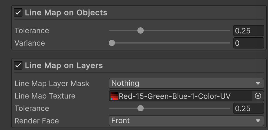
Line Map on Layers interface
If you go to the Debug Output menu and select Line Map On Layers, you will see the outlines generated by the Line Map on Layers source.
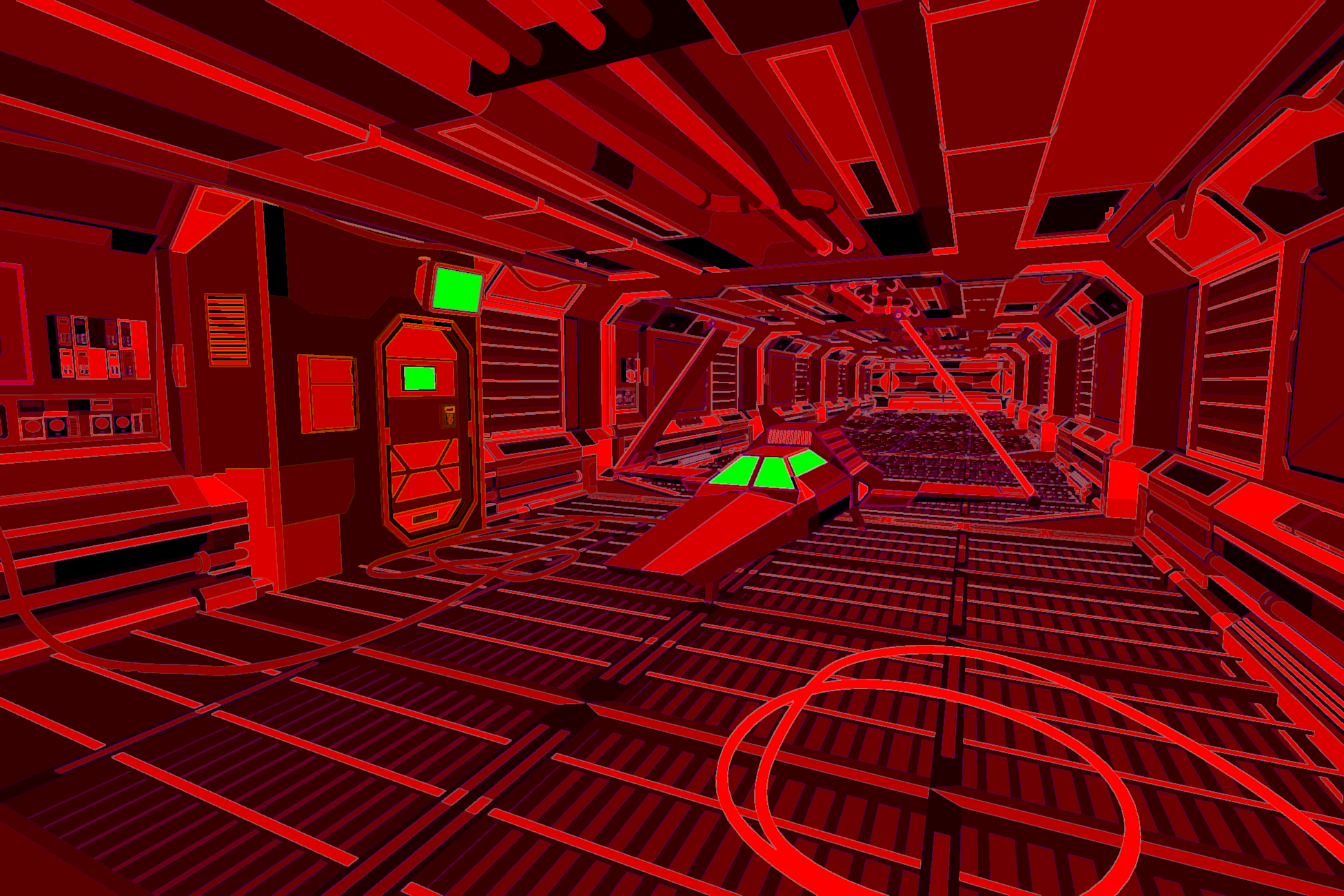
Line Map On Layers pass selected in Debug Output
Parameters
- Line Map Layer Mask - Lets you choose the layer on which the objects will have an outline generated by the Line Map on Layers source.
- Line Map Texture - Sets the texture to be used as source of color differences for the pre-mapped faces of the mesh. It is described in detail further on this page.
- Tolerance - Tells how different should be the red colors to cross the threshold and generate a line.
- Render Face - Lets you choose whether to render Front, Back or Both faces of the mesh.
Best Practices
Line Map Texture
When unwrapping the model in a 3D editor software, you can distribute the faces of the mesh in the UV space in a way that those faces that you want to have a shared outline are placed in the differently colored areas of the texture. If you don’t want two faces to have an common outline, you can place them in the same colored area of the texture. The texture should be primarily in red color.
Of course, you can have any texture you’d like, as soon as there are at least two flat areas with non-identical colors. Line Kit looks at the red channel but you can have textures of any color. In our sample scenes we used a texture with tiles filled with multiple shades of red. There are also the variations with 16 colors or the ones where a corner tile is filled with 100% green and 100% blue colors.
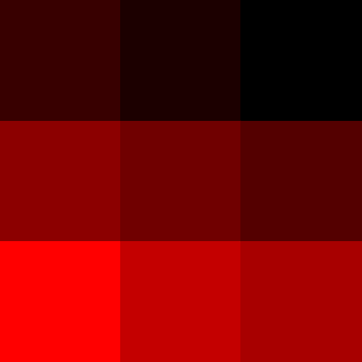
Line Map on Layers Texture - 9 shades of red
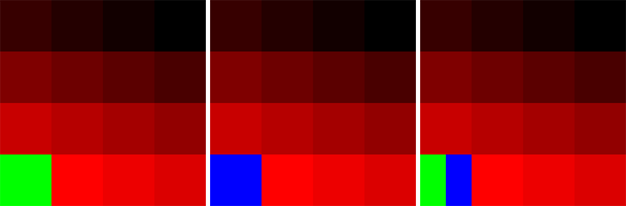
Variations of Line Map Texture - 15 shades of red with green and blue
You can have as many shades (tiles) of red as you’d like. We found that 9 is sufficient for the simple models and 15 or 16 red tiles are enough to distribute the faces on a complex model so that no two red shades are visually next to each other in any moment of the camera alignment. The more tiles you have the easier it is to distribute the UV faces over the texture space.
The texture doesn’t have to be very big — it is not meant for rendering but rather for internal processing of the outines.
Please have a bit of a margin when placing the UV faces in the 3D editor. If the edges between two shades are blurry and the UV face touches that blur, the outlines will get messy in that area.
We found that it is quite difficult to distribute the faces in the UV space if the same red texture in a 3D editor like Blender. Turns out, our eyes can’t distinguish the shades of red very well and most likely there will be some faces that will be placed in the wrong shade. So you can have a texture with very different colors — just to be used during the modeling and UV unwrapping. Like this one:
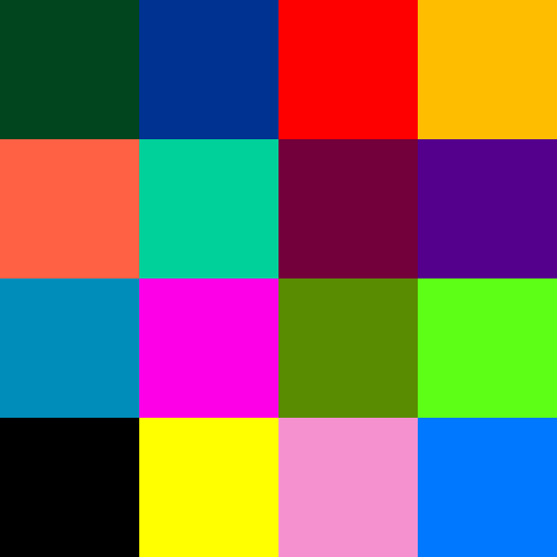
Texture with 16 visually different colors to be used for UV unwrapping
It is much easier to distribute the faces in the UV space when you have a texture with very different colors. You can still use the primary texture with red shades for the final rendering in Unity.
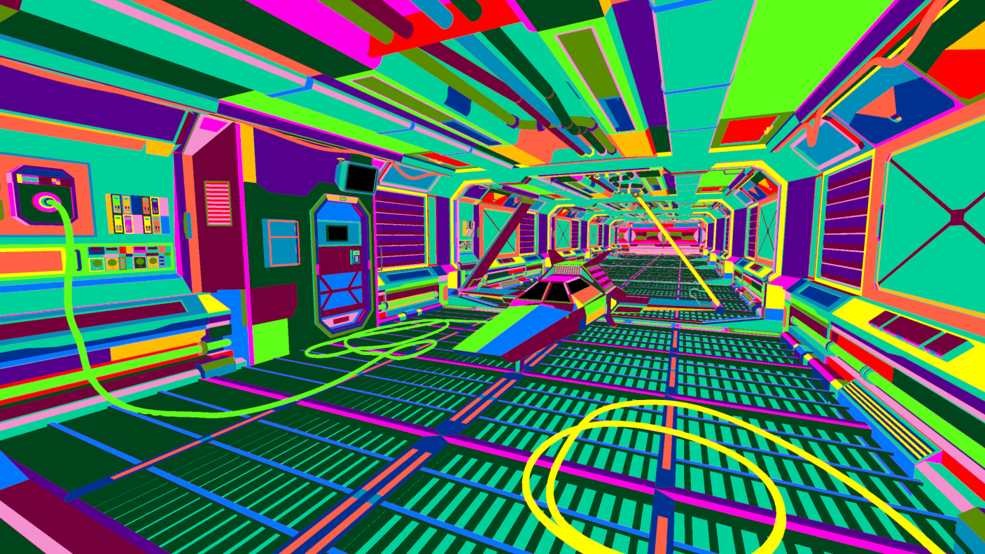
Scene with the debug texture
An important thing to note is that the texture Import Settings in Unity contains the Compression and Filter Mode parameters. You should set the Compression to None and Filter Mode to Point (no filter). This way the texture will be rendered pixel-perfect and the outlines will be sharp and glitch-free.
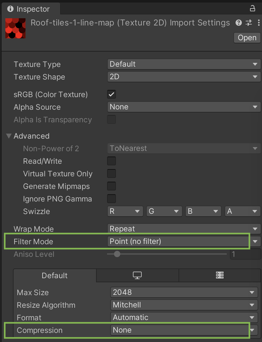
Texture Import Settings
Example Process
Here is a step-by-step process of creating inner lines on an object using a Line Map. We will use a simple model consisting of a few primitives for the sake of simplicity.
Starting point
We start with the Depth and Normal lines. They generally outline parts of the object, but there is no way to precisely control inner lines. Plus, there are inner parts in the mesh that these two methods can’t outline.
Simple inner lines with Line Map
Here we use a simple Line Map texture with 9 shades of red. The faces of the object are distributed over the texture in a way that the faces that we want to have a shared outline are placed in the differently colored areas of the texture. The faces that we don’t want to have a shared outline are placed in the same colored area of the texture.
This results in a nice inner lines on the object exactly where we want them.
Line around parts of the object
If the model is a bit more complex and has curvatures in it, the Depth and Normal lines can produce artifacts. Of course, you can fine-tune them with the Tolerance parameter for both Depth and Normals. We decided to use a Line Map to outline the whole model.
Please note that using Line Map doesn’t mean that you can’t use Depth and Normals. You can and should use them all together. The models can have different Line Map materials to avoid such artifacts, furthermore, many normals related issues can be fixed in 3D editor during the modeling stage. It’s just one of our examples.
Blue and green channels of Line Map
Here we show the effect of having the parts of the model mapped onto blue and green parts of our texture. The blue channel of the Line Map texture is used to remove the outline. The green channel is used to fill the face with the color of the outline.